7. Hibernation Mode configuration
To configure DA14531 device to hibernation mode, follow the steps mentioned below.
Open the proximity reporter project from: …projects/target_apps/ble_examples/prox_reporter/Keil_5
Open the file user_proxr.h which is under the user_app folder.
Define CFG_APP_GOTO_HIBERNATION to select the sleep mode that the device enters after completion of advertisement.
#if defined (__DA14531__)
#define CFG_APP_GOTO_HIBERNATION
The device can enter the hibernation mode after booting from either SPI Flash, OTP or SysRAM.
7.1. Using SPI Flash
To enter the hibernation after booting from SPI Flash, the following software modification needs to be done, starting with user_proxr.h file
In the Hibernation mode configuration, switch off all the three RAM blocks to reduce power and remap the address 0 to ROM as shown below,
/****************************************************************************************
* Hibernation mode configuration                                                       *
****************************************************************************************/
#define CFG_HIBERNATION_RAM1            PD_SYS_DOWN_RAM_OFF
#define CFG_HIBERNATION_RAM2            PD_SYS_DOWN_RAM_OFF
#define CFG_HIBERNATION_RAM3            PD_SYS_DOWN_RAM_OFF
#define CFG_HIBERNATION_REMAP           REMAP_ADDR0_TO_ROM
#define CFG_HIBERNATION_PAD_LATCH_EN    false
#endif
7.2. Using SysRAM
To enter the hibernation after booting from SysRAM, the following software modification needs to be done, starting with user_proxr.h file
In the Hibernation mode configuration, switch ON all the three RAM blocks and remap the address 0 to SysRAM as shown below,
/****************************************************************************************
* Hibernation mode configuration                                                       *
****************************************************************************************/
#define CFG_HIBERNATION_RAM1            PD_SYS_DOWN_RAM_ON
#define CFG_HIBERNATION_RAM2            PD_SYS_DOWN_RAM_ON
#define CFG_HIBERNATION_RAM3            PD_SYS_DOWN_RAM_ON
#define CFG_HIBERNATION_REMAP           REMAP_ADDR0_TO_RAM1
#define CFG_HIBERNATION_PAD_LATCH_EN    false
#endif
7.3. Using OTP
To enter the hibernation after booting from OTP, the following software modification needs to be done, starting with user_proxr.h file
In the Hibernation mode configuration, switch off all the three RAM blocks to reduce power and remap the address 0 to ROM as shown below,
/****************************************************************************************
* Hibernation mode configuration                                                       *
****************************************************************************************/
#define CFG_HIBERNATION_RAM1            PD_SYS_DOWN_RAM_OFF
#define CFG_HIBERNATION_RAM2            PD_SYS_DOWN_RAM_OFF
#define CFG_HIBERNATION_RAM3            PD_SYS_DOWN_RAM_OFF
#define CFG_HIBERNATION_REMAP           REMAP_ADDR0_TO_ROM
#define CFG_HIBERNATION_PAD_LATCH_EN    false
#endif
In user_periph_setup.h file, configure the GPIO that would be used to wake-up the device from hibernation mode. In this case we have chosen P0_5 as the wake-up GPIO.
/****************************************************************************************/
/* Wake-up from hibernation configuration                                               */
/****************************************************************************************/
#if defined (__DA14531__)
    #define HIB_WAKE_UP_PORT        GPIO_PORT_0
    #define HIB_WAKE_UP_PIN         GPIO_PIN_5
    #define HIB_WAKE_UP_PIN_MASK    (1 << HIB_WAKE_UP_PIN)
#endif
The advertisement period can be changed in the user_config file, like so,
/*
 ****************************************************************************************
 *
 * Default handlers configuration (applies only for @app_default_handlers.c)
 *
 ****************************************************************************************
 */
static const struct default_handlers_configuration  user_default_hnd_conf = {
    // Configure the advertise operation used by the default handlers
    // Possible values:
    //  - DEF_ADV_FOREVER
    //  - DEF_ADV_WITH_TIMEOUT
    .adv_scenario = DEF_ADV_WITH_TIMEOUT,

    // Configure the advertise period in case of DEF_ADV_WITH_TIMEOUT.
    // It is measured in timer units. Use MS_TO_TIMERUNITS macro to convert
    // from milliseconds (ms) to timer units.
    .advertise_period = MS_TO_TIMERUNITS(18000), //this is for 18s

    // Configure the security start operation of the default handlers
    // if the security is enabled (CFG_APP_SECURITY)
    // Possible values:
    //  - DEF_SEC_REQ_NEVER
    //  - DEF_SEC_REQ_ON_CONNECT
    .security_request_scenario = DEF_SEC_REQ_NEVER
};
This will configure the advertising period as 18s after which the device will enter the hibernation mode. To wake-up from hibernation use P0_5 which was configured before as wake-up GPIO.
Save all the changes done in the project and Compile (F7).
Program the DA14531 using the compiled hex file and boot from flash.
To do this, please refer to SmartSnippets User Manual ,
Chapter 8 - to download and boot from SysRAM,
Chapter 12 - To program and boot from OTP,
Chapter 13 - To program and boot from SPI Flash.
Refer to the hibernation mode example that shows the use-cases of SPI, OTP and SysRAM to get the complete picture of its usage.
7.4. Measuring the Hibernation sleep current
In order to measure the hibernation sleep current over a digital multimeter, increase the advertising interval in the proximity reporter project under user_config.h. Follow the steps mentioned below:
Open the file user_config.h which is under the user_config folder.
Change the default handlers configuration to advertise the device with a timeout, by configuring .adv_scenario to DEF_ADV_WITH_TIMEOUT and changing the timeout value to 18s for example, .advertise_period = MS_TO_TIMERUNITS(18000), as shown below,
/*
 ****************************************************************************************
 *
 * Default handlers configuration (applies only for @app_default_handlers.c)
 *
 ****************************************************************************************
 */
static const struct default_handlers_configuration  user_default_hnd_conf = {
    // Configure the advertise operation used by the default handlers
    // Possible values:
    //  - DEF_ADV_FOREVER
    //  - DEF_ADV_WITH_TIMEOUT
    .adv_scenario = DEF_ADV_FOREVER, //advertising forever

    // Configure the advertise period in case of DEF_ADV_WITH_TIMEOUT.
    // It is measured in timer units. Use MS_TO_TIMERUNITS macro to convert
    // from milliseconds (ms) to timer units.
    .advertise_period = MS_TO_TIMERUNITS(18000), //this is for 18s

    // Configure the security start operation of the default handlers
    // if the security is enabled (CFG_APP_SECURITY)
    // Possible values:
    //  - DEF_SEC_REQ_NEVER
    //  - DEF_SEC_REQ_ON_CONNECT
    .security_request_scenario = DEF_SEC_REQ_NEVER
};
This will configure the advertising period as 18s after which the device will enter the hibernation mode. The device can wake-up from hibernation mode by programming the trigger mechanism for wake-up as mentioned in the previous section.
Save and Compile the project
Follow the steps here in chapter 12 OTP Programmer or chapter 13 SPI Flash programmer to program the device either in FLash or OTP, and then boot from there.
Use a digital multimeter, connect the positive of multimeter to J9[4] and the negative to J9[3] of the motherboard, as shown in the figure below,
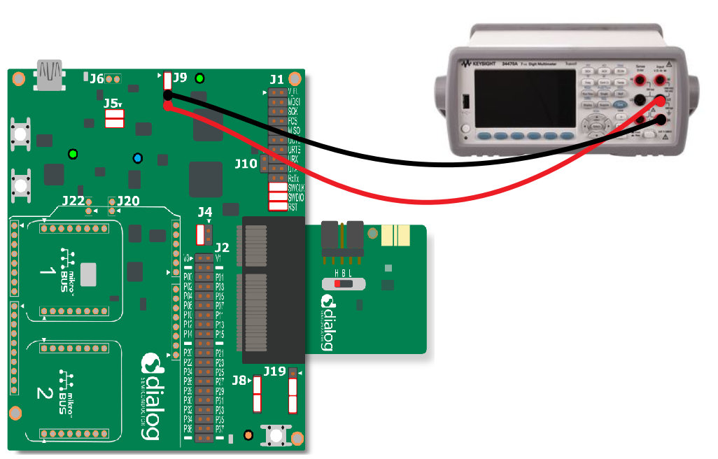
Figure 15 Hibernation sleep power measurement
Observe the hibernation sleep current value displayed in the meter. The typical numbers are mentioned below where the IBAT_LOW values are for the Boost mode and the IBAT_HIGH values are for Buck mode.

Figure 16 Deep sleep power numbers in buck and boost mode
To change to Boost mode, use the switch on the daughterboard and put it to L. On the motherboard, put the jumper on J4[1-2], as shown in sleep mode overview chapter.
Repeat the steps from 1 to 5